






FFC vs FPC vs RFC: How to Choose the Right Solution
When you design an electronic product, engineering and purchasing face the same question: which flexible interconnect fits this job? FFC (flexible flat cable), FPC (flexible printed circuit) and RFC (round flat cable) each solve a different problem. Knowing the difference lets you decide on performance, reliability and cost.
FFC is a laminated cable with parallel FLAT copper conductors in PET or polyimide. It is built for simple point-to-point links, typically into a ZIF/LIF connector. Strengths: low cost, fast tooling, pitch 0.3–2.54 mm, 4–120+ pins, thin profile. Typical uses: printers, scanners, consumer electronics, automotive displays, simple board-to-board links.
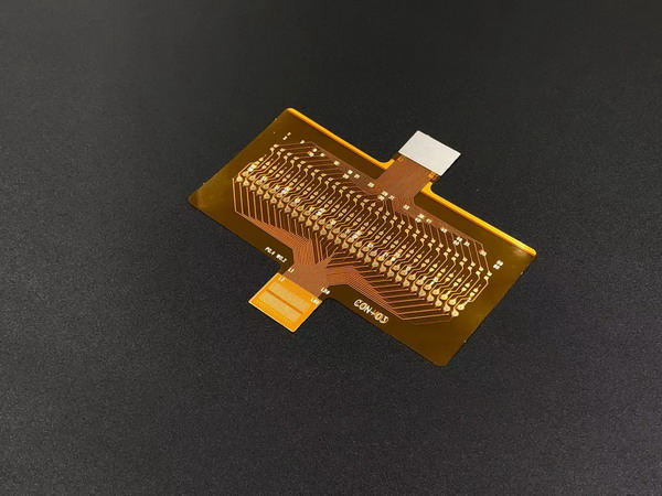
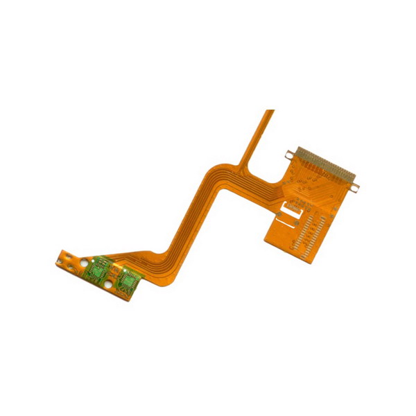
FPC is an etched circuit on polyimide — a flex board, not only a connector. Unlike FFC’s parallel conductors it can route freely, carry components and use multiple layers. Strengths: dense routing, line/space to 0.05 mm, dynamic flex with coverlay. Typical uses: phones, wearables, medical modules, automotive electronics, high-density interconnects.
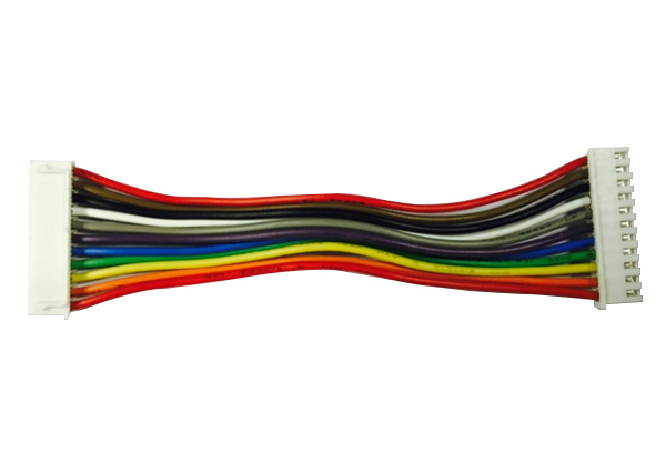
RFC (round flat cable / round-end flat cable) uses ROUND conductors at one or both ends so you can through-hole or wave-solder to the PCB — no connector needed. Also called a flexstrip jumper or solder jumper. A hybrid RFC is round on one end and flat on the other for ZIF. Strengths: vibration-resistant solder joint, pitches 1.0 / 1.25 / 1.27 / 2.0 / 2.54 mm, specified tinning length, PET/PI/PVC insulation. Typical uses: appliances, automotive lighting, industrial control boards, compact consumer PCBs.
In manufacturing, FFC laminates flat copper between films and scales well. FPC etches polyimide and needs more tooling. RFC forms and tins round ends on a flat insulated body — simpler than a rigid-flex PCB, with pitch, tinning length and concentricity as the process keys.
Design freedom: FFC stays on parallel paths but can fold, slit and take many terminations. FPC allows arbitrary traces, parts and layers. RFC’s freedom is at the ends — one or both sides round, or hybrid ZIF — not in complex routing. Choose FPC when the circuit must snake.
Space and weight: FFC is thinner and lighter than a round-wire harness. FPC can drop board-to-board connectors by routing in 3D. RFC removes the connector at the soldered end, saving socket height and mating tolerance — often the cleanest option on appliance and industrial boards.
Reliability: FFC suits static or limited flex, typically over 100,000 bend cycles. FPC with PI coverlay can exceed 900,000 dynamic cycles. RFC reliability sits in the solder joint — through-hole or wave solder for vibration. High-cycle dynamic flex remains an FPC job.
Cost: FFC is usually cheapest for simple point-to-point. FPC costs more in tooling and process in exchange for routing and components. RFC sits between them: round-end forming costs more than a standard FFC, but is often cheaper than an FPC or an extra connector pair.
Pick FFC when point-to-point is enough, cost and speed matter, and standard pitch is acceptable. Pick FPC when you need complex routing, components, multilayer or high-cycle flex. Pick RFC when you must solder round conductors to the PCB with no connector, or need a hybrid round-to-flat ZIF — appliances, automotive lighting, industrial boards, vibrating joints.
Nurwire manufactures all three, so the recommendation can follow the application rather than a single product line. Share the drawing and we will help you choose.