






FPC & RFC Design Guide for Engineers
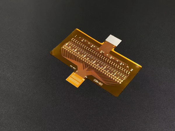
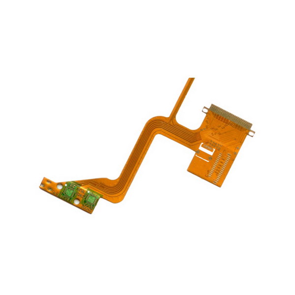
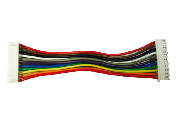
Designing an FPC (flexible printed circuit) and an RFC (round flat cable) means looking at materials, geometry and process together. Unlike a rigid PCB, a flex circuit must bend without losing electrical performance. An RFC is not a rigid-flex board: it is a jumper with round conductors formed at the ends for soldering.
Materials: most FPC uses polyimide for heat, chemicals and mechanics; PET fits lower-demand, cost-sensitive jobs. PI about −40°C to +105°C, PET −40°C to +85°C. Copper: 1/2 oz for fine pitch, 1 oz standard, 2 oz for high current. PI coverlay protects FPC best. RFC uses tin-plated round copper and PET, PI or PVC film on the flat body.
FPC stack-up can be single-sided (simplest, cheapest), double-sided or multilayer. Layer count, order (critical signals inside) and reference planes matter for impedance.
FPC routing: line/space to 0.05 mm; avoid sharp corners; keep spacing even; keep sensitive traces away from noise; match differential pairs; size vias and add teardrops.
Bend radius and flex life: single-layer FPC about 3× thickness, double-sided 6×, multilayer 10×. For dynamic flex, enlarge the radius and use thinner copper. PI-coverlay FPC can exceed 900,000 cycles.
RFC design keys are at the round end: align pitch 1.0 / 1.25 / 1.27 / 2.0 / 2.54 mm to the PCB hole pattern; leave enough tinning length for wetting; add strain relief from round to flat; hybrid RFC puts ZIF on the flat end; keep solder joints away from tight bends. Do not copy rigid-flex via and coverlay rules onto an RFC jumper.
FPC DFM: mechanical holes about 0.2 mm min, PTH about 0.3 mm, line/space 0.05 mm min, annular ring 0.05 mm, coverlay clearance around pads, stiffeners off the bend zone. RFC DFM: tinning length, pitch tolerance, round-end concentricity, strain relief and panelization that survives wave solder.
Impedance: size traces to the target, e.g. USB ~90 Ω, LVDS ~100 Ω; differential pairs to differential impedance (HDMI ~100 Ω). Manufacturing tolerance typically ±10%.
Common mistakes: too-small bend radius on FPC, traces across the bend axis, vias in the flex, weak coverlay, sharp corners — and on RFC, too-short tinning, no strain relief, treating the part as a rigid-flex stack.
Validation covers electrical (continuity, shorts, insulation, hi-pot), mechanical (dynamic flex, insertion, peel), environmental (thermal cycle, humidity, shock, salt spray) and solderability of RFC round ends.
An experienced manufacturer such as Nurwire can give DFM feedback, material advice and fast samples early. Contact us for your FPC and RFC design.